Control Container Design Example
WLOADCTL organizes and manages jobs through job controllers. Job controllers are divided into MainFlow, SubFlow, and Timer. If there are complex dependency relationships between jobs, please use MainFlow or SubFlow to organize job sets. Timers are more suitable for scenarios where jobs have no relationships with each other and need to be scheduled at fixed frequencies.
Note: After a SubFlow runs from start to finish, it will exit. However, SubFlows can be called by MainFlow or Timer to achieve automated scheduling.
The following is a simple SubFlow control container design example (hereinafter referred to as SubFlow) to help you understand the basic operations of Designer and some feature characteristics of WLOADCTL.
Design Example Description
1. Job Program List
| Program Name | Program Type | Program Entry Parameters |
|---|---|---|
| filewatch1 | filewatch | /home/myfile/fileisok.flg |
| dsjob1 | datastage program | $(workspace)/etl/dsjob1 |
| oraproc1 | oracle stored procedure | pkg.procdure1 |
| dsjob2 | datastage program | $(workspace)/etl/dsjob2 |
| dsjob3 | datastage program | $(workspace)/etl/dsjob3 |
2. Dependency Relationships
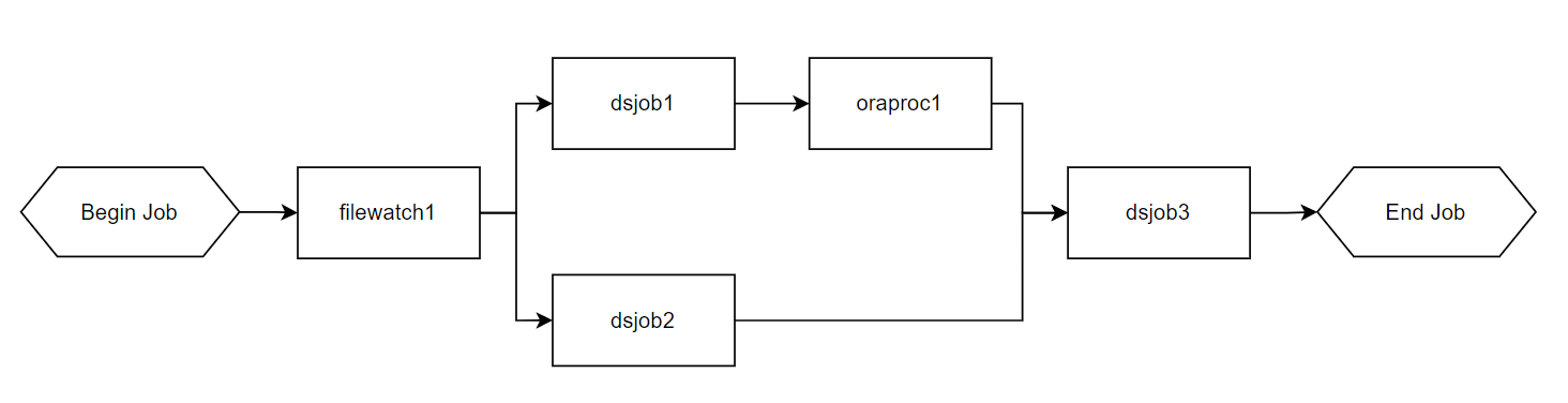
3. Trigger Method
File arrival trigger
Create a New SubFlow
Click the + icon directly in the control container to create, or click Select to create a container, as shown in the figure:
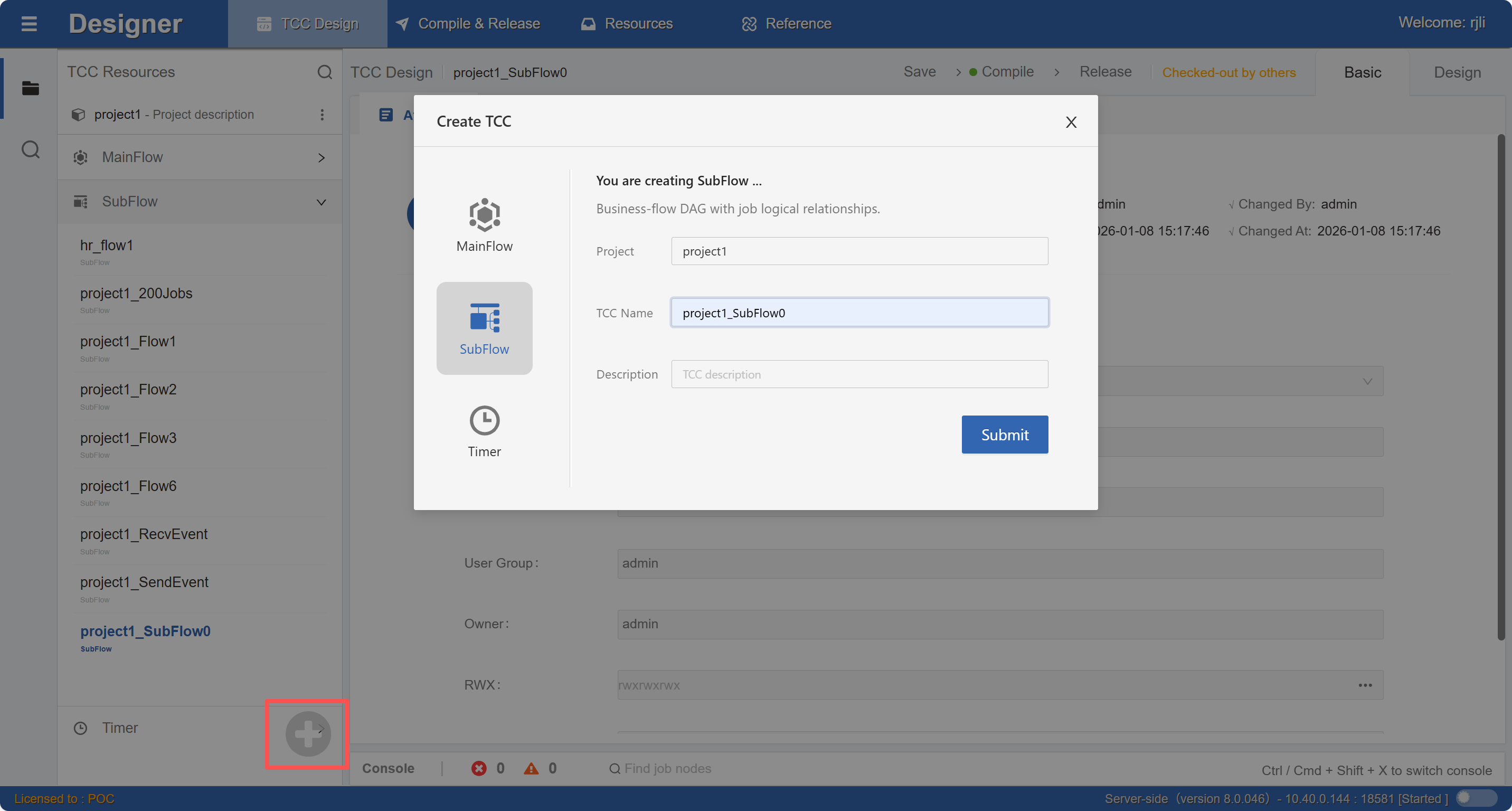
In the window, select SubFlow, enter the name and description, and click the Submit button to complete creation.
Private Variable Design
To ensure scheduling flexibility and portability, when defining jobs, you can introduce parameters for the program corresponding to each job.
1. Enter the Private Variable Edit Interface
Double-click the Variables item in the project1_SubFlow0 workflow in the resource explorer, as shown in the figure:
In the Control Container Resources list on the left, select the container to which you want to add variables, click `` to enter the checkbox selection, and select Private Variable, as shown in the figure:
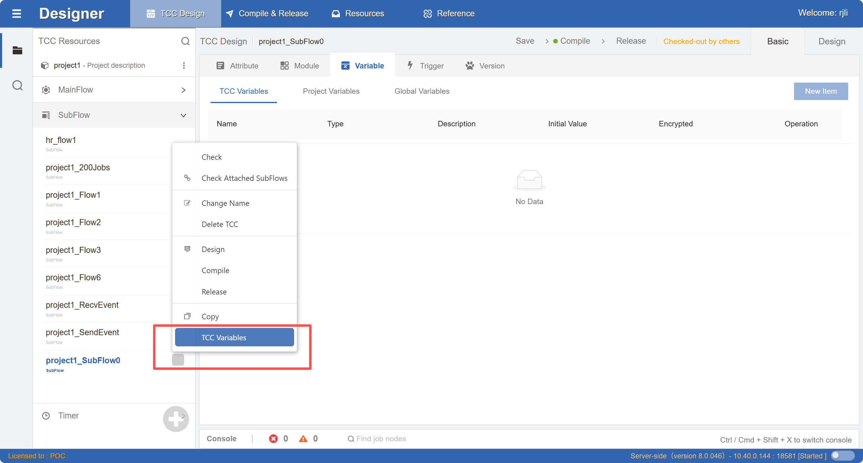
2. Add Variables
The result after adding variables is as follows:
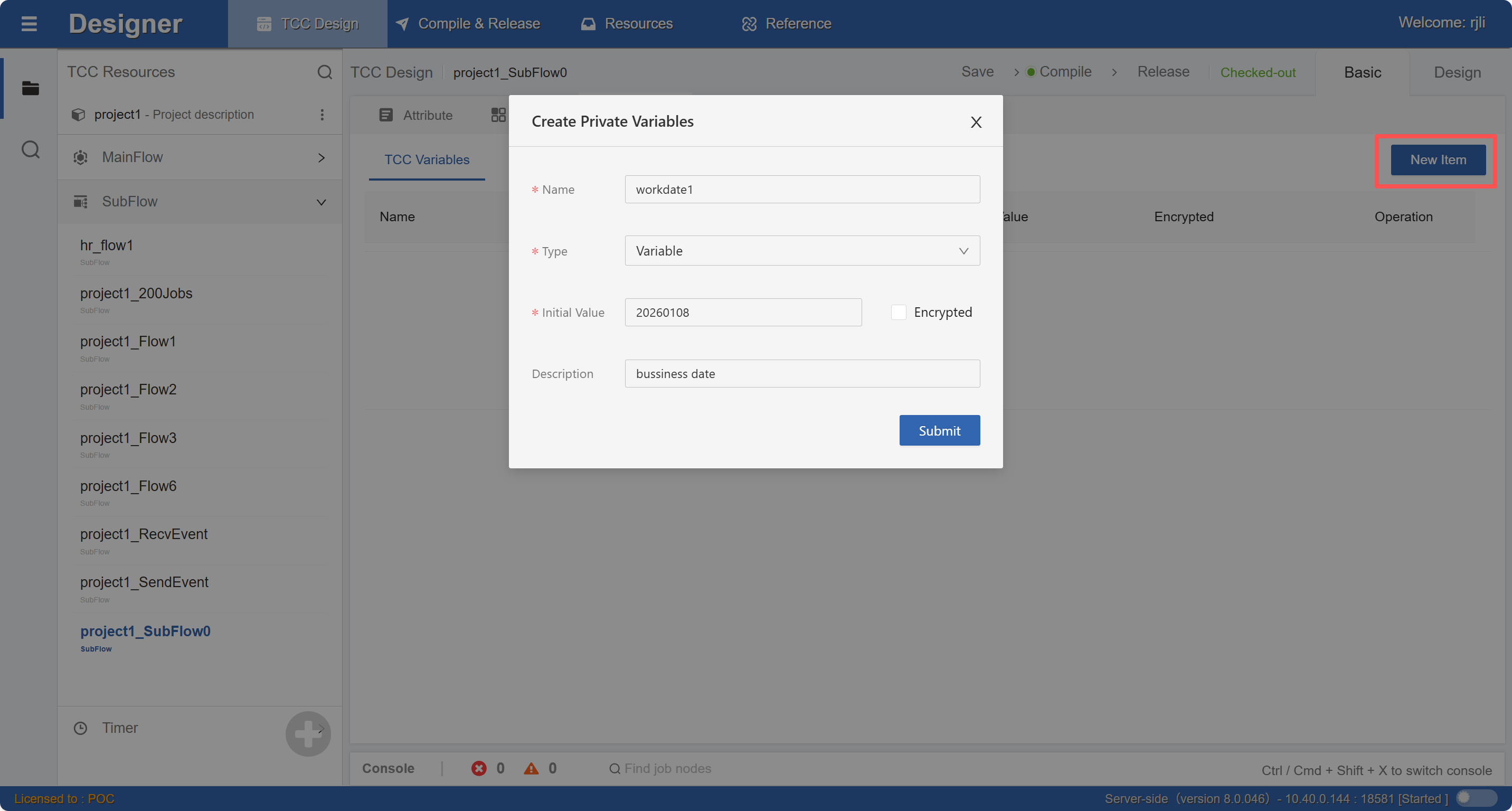
Press Ctrl+S or click the Submit button in the popup to save the edited variable information. Similarly, the addition method and steps for Project Variables / Platform Constants of the container are the same.
Graphical Design Mode
This feature provides switching between graphical design mode and module code design, a job node search box, the container design toolbar, component toolbox, job node resource tree, and the job properties panel.
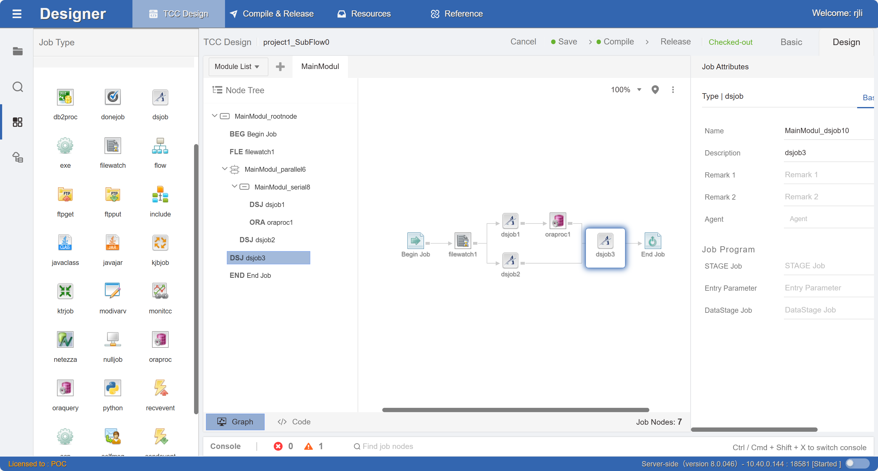
Drag and Drop to Add Job Nodes
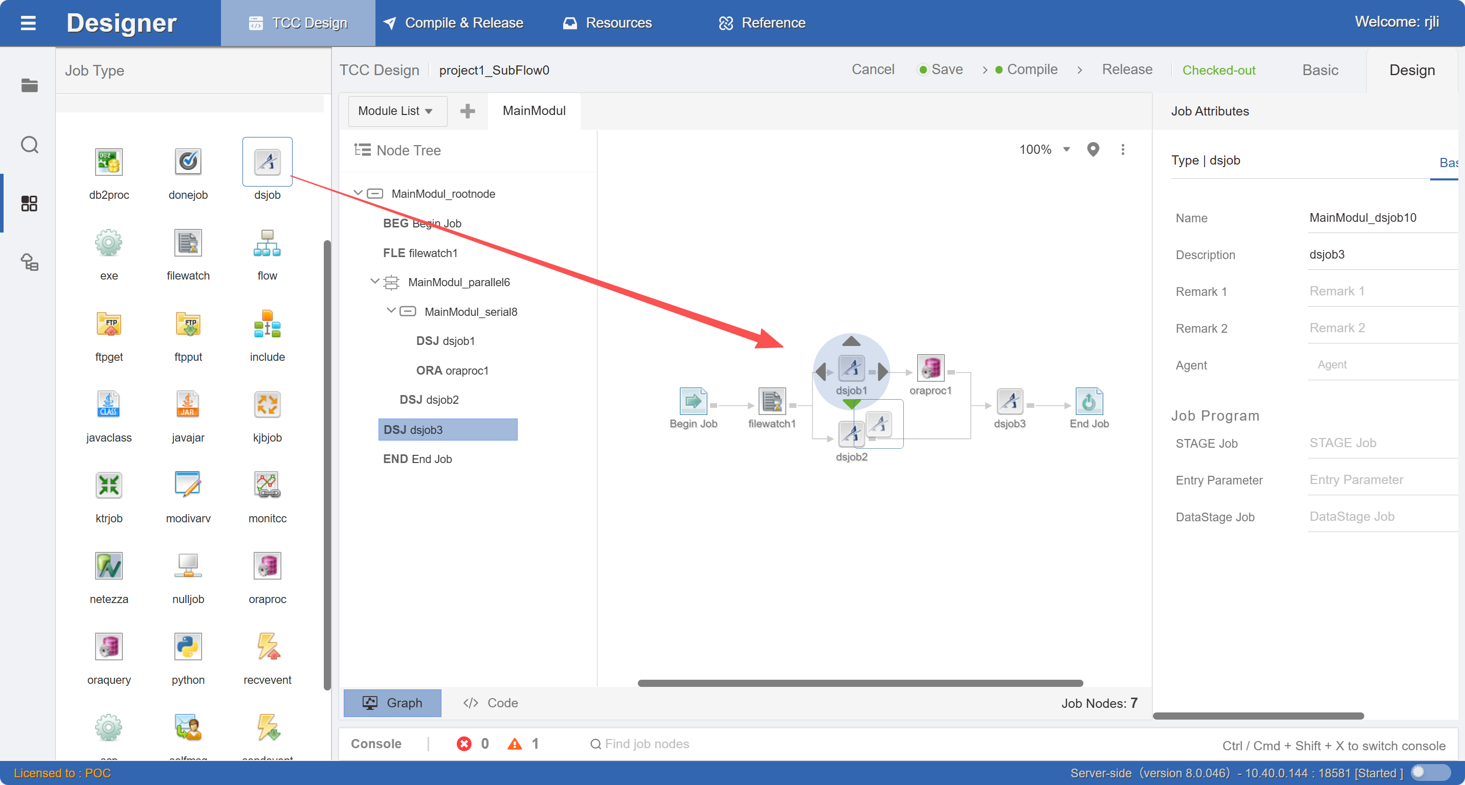
When adding job nodes to a workflow, drag the corresponding job type directly from the toolbox to the workflow diagram on the right. Note: When dragging to a node, you can select the placement direction:
- Top - Parallel relationship
- Bottom - Parallel relationship
- Left - Predecessor dependency relationship
- Right - Successor dependency relationship
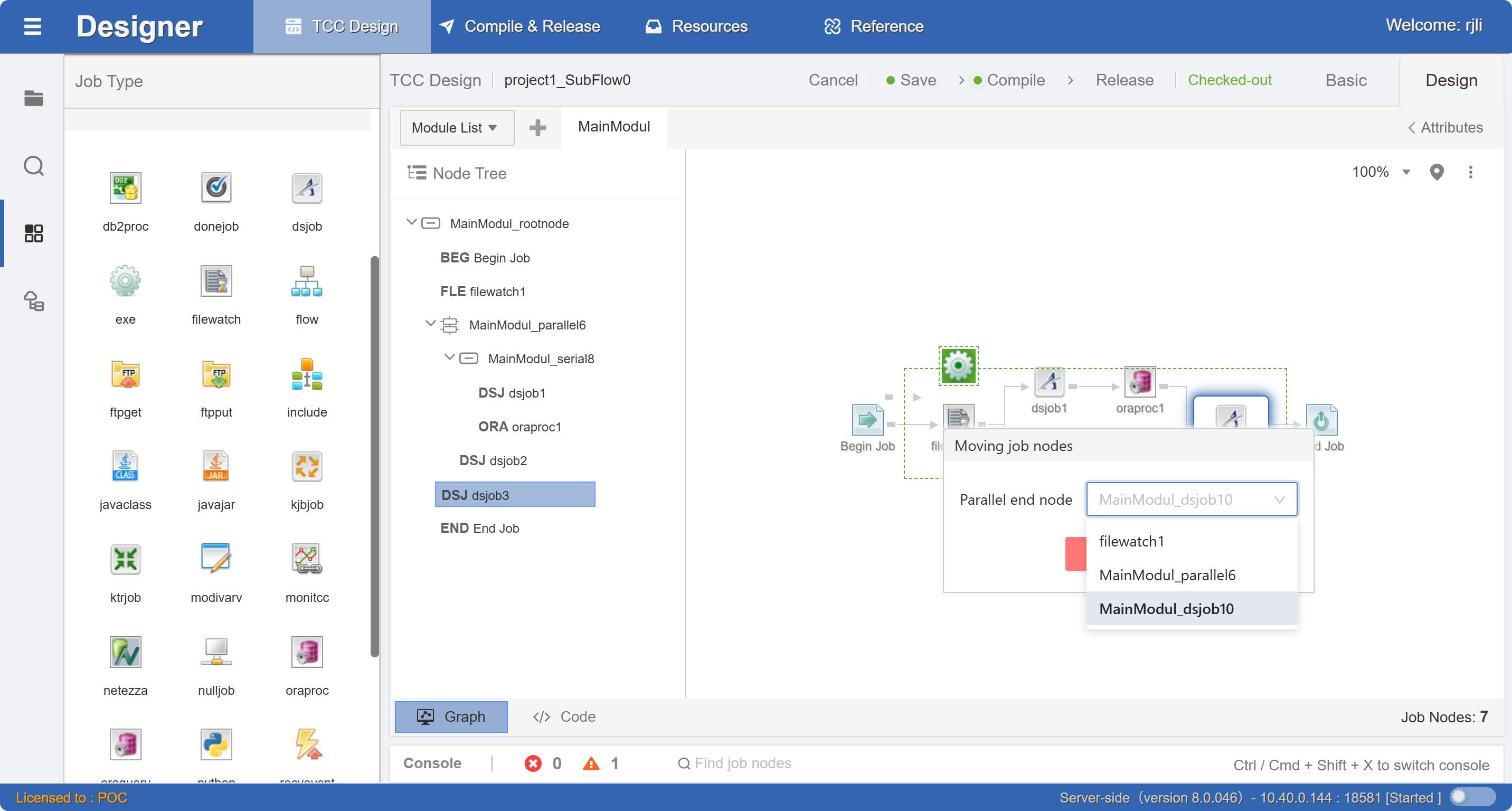
Parallel relationships also require selecting the end node of the parallel branch, as shown in the figure:
Edit Job Node Properties
Since job properties are relatively numerous, WLOADCTL divides job properties into Basic and Advanced categories for simplicity and ease of use, as shown in the figure:
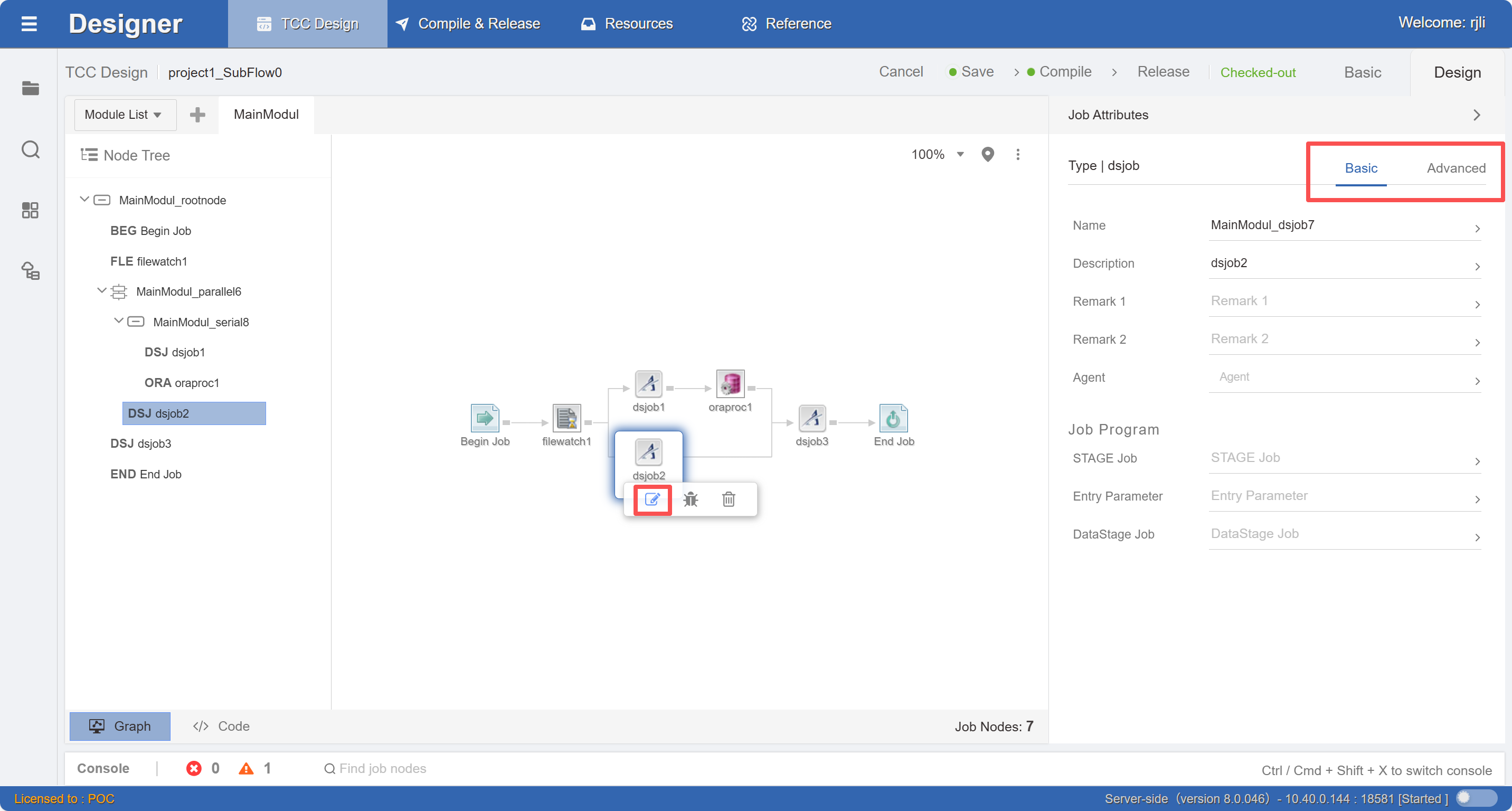
Through this editor, you can modify various basic properties of jobs and various scheduling control strategies. The properties corresponding to each job type may be different. Here, the file arrival job type is used, and you only need to set the para parameter to specify the file path. For more information about job properties, please refer to the WLOADCTL Product Documentation - Code Rule Syntax document.
When defining job node properties, you need to understand the difference between ordinary properties and composite properties. Define each job node of the flowbuss_Flow4 workflow as follows:
| Name | progname | para (Program Entry Parameters) | exppara (Program Environment Parameters) |
|---|---|---|---|
| fielwatch1 | -- | /home/TASKCTL/ods/$(workdate1)/ fileisok.flg | -- |
| dsjob1 | dsjob1 | $(workdate1) | projectname=$(projectname) |
| oraproc1 | pkg.procdure | $(workdate1) | $(dbname),$(dbuser),$(dbpassword ) |
| dsjob2 | dsjob2 | $(workdate1) | projectname=$(projectname) |
| dsjob3 | dsjob3 | $(workdate1) | projectname=$(projectname) |
Job Resource Tree
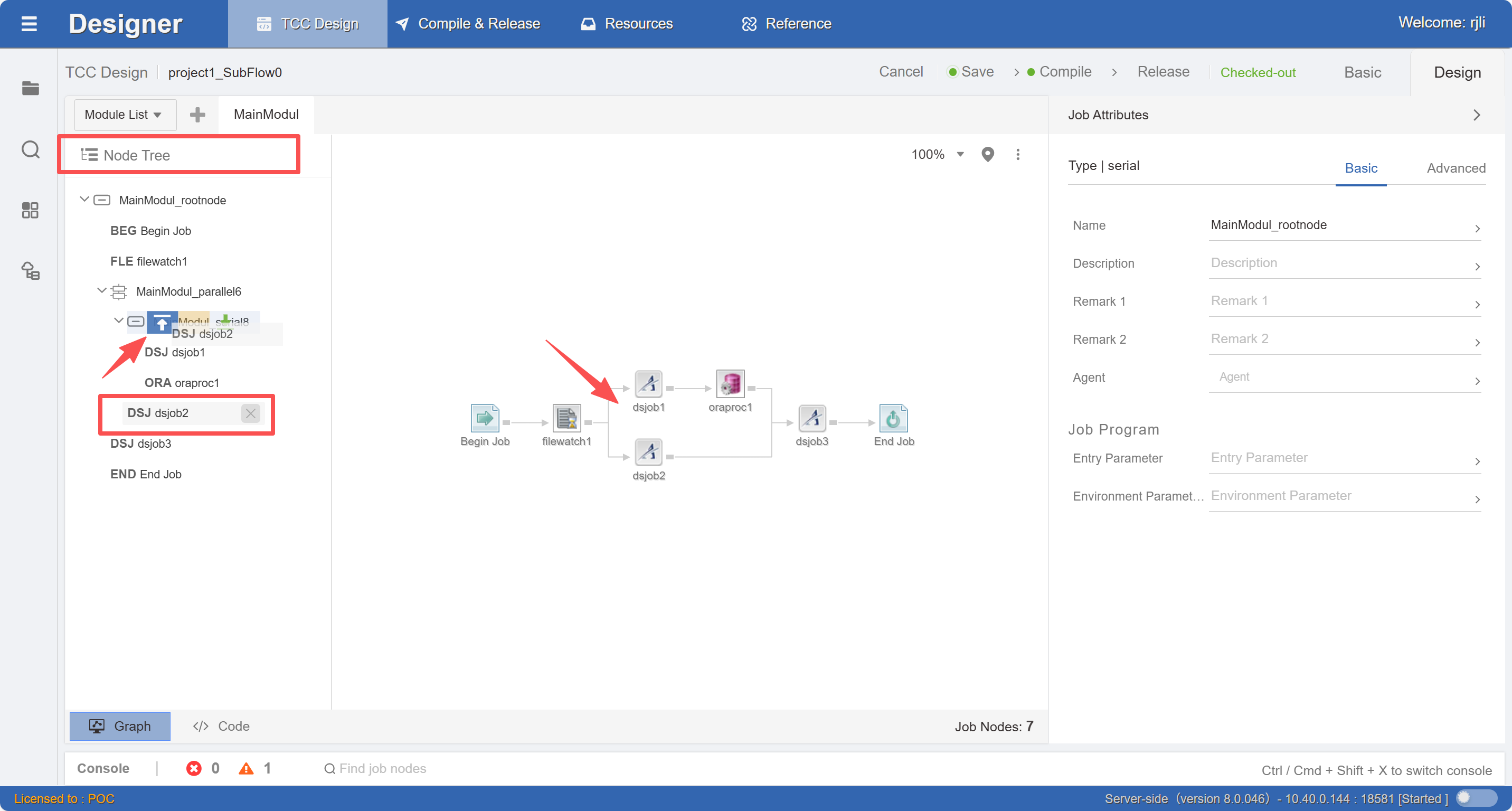
Job relationship configuration can also be completed through the job resource tree. The job node resource tree assists the workflow diagram. Select serial/parallel group job nodes and drag the entire group to adjust serial/parallel relationships, as shown in the figure: